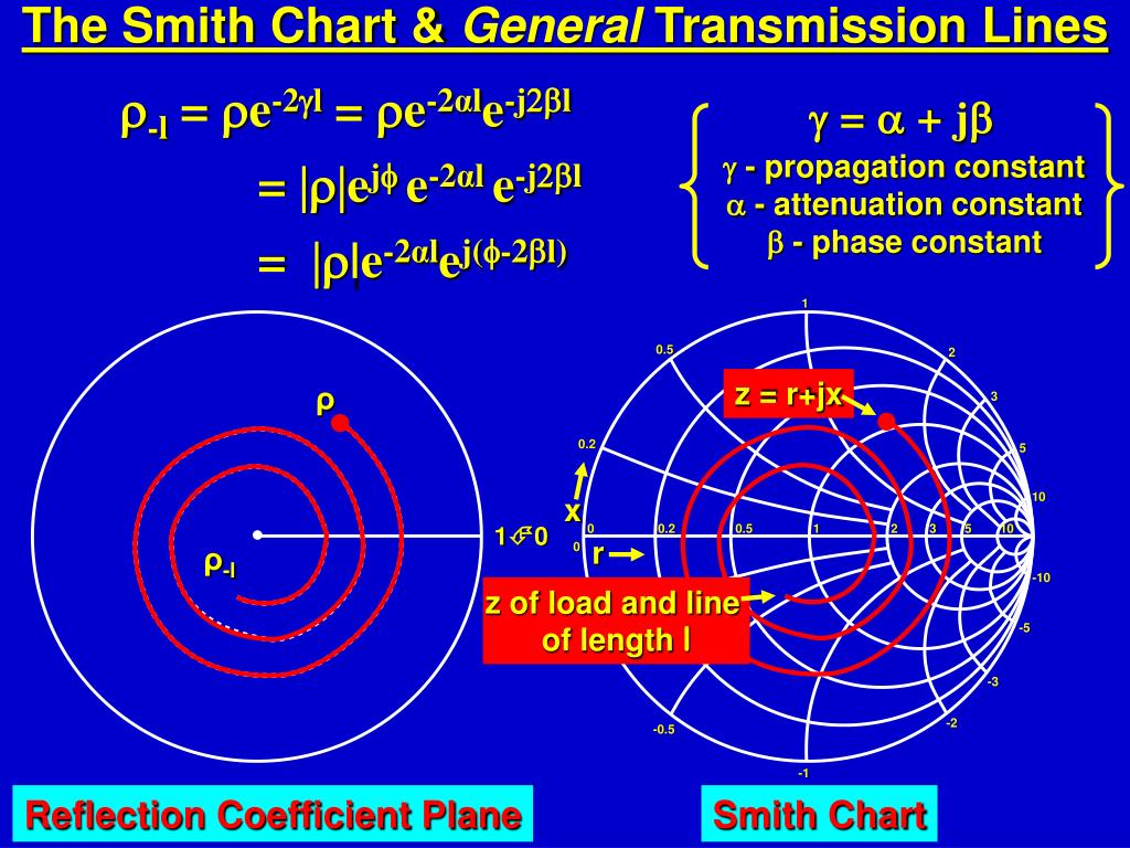


widely used when tuning or verifying the performance of networks.still useful to help visualize complex impedances, especially as a function of frequency.It was't until about twenty years ago when I started researching the chart did I find the truth. In my younger days I was told that Carl Smith, of the consulting engineering firm Smith Electronics, Cleveland, Ohio, was the inventor. Although calculators and computers can now easily give answers to the problems the Smith chart was designed to solve, this great chart still remains a valuable tool. The Smith Chart was created by an RF engineer at R.C.A. the Smith Chart lets you solve the problem graphically with a compass, ruler and pencil Smith chart is really just a plot of complex reflection coefficient overlaid with a normalized characteristic impedance (1 ohm) and/or admittance (1 mho or siemen) grid.pre-computers this was an intensive process.the most common are impedance matching and the design of matching networks.Compute the required circuit Q by (1 + Q2) m, or 3 L I F1. We didn't try to put every last line on the chart, most times you use a Smith Chart you are more interested in approximate locations (is it short or an open, is it capacitive or inductive, etc. It's just a matter of creating equations for semi-circles, something any nerd can do. In 1969 he published the book Electronic Applications of the Smith Chart: In Waveguide, Circuit, and Component Analysis, a comprehensive work on the subject. This Lecture: Smith Chart and S-Parameters Quick notes about matching networks Smith Chart basics Scattering Parameters EE142-Fall 2010 4 Matching Network Design 1. New for January 2008 We've created a Smith chart within Excel.When asked why he invented the chart, Smith explained, "From the time I could operate a slide rule, I've been interested in graphical representations of mathematical relationships.".Named after Philip Hagar Smith, first described in January 1939 The normalized input impedance for that transmission line is read from the Smith Chart to be 1 - j0.75. This represents the length of the transmission line, where is the wavelength in the transmission line. A description of the Smith Chart was first published in 1939. It can also be employed to help build accurate impedance-matching systems along with other functions. Main source material from Rohde & Schwarz Smith Chart Example The distance moved on the scale is 0.348 - 0.198 0.15. Smith (1905-1987), the chart is used as a problem-solving tool to assist Hams in calculating the feed-point impedance of an antenna.


 0 kommentar(er)
